Drawing the structure
S-FRAME: Joint tool (p2993), Member Definition tool (p3014), Continuous Member tool (p2982), Support tool (p3099), Physical members (p198).
Joint tool (J)
Click a grid point, a point on a member, or anywhere on the working plane (rounded to the free-point spacing). The Databar also takes typed X Y Z. A dragged box adds a joint at every grid point inside it (fence-adding).
Joint tool (J)
S-FRAME: Joint tool (p2993–2996).
Click grid points, points on members or free points on the working plane, or type X Y Z and press OK. A Delta X Y Z with a Generate count adds a sequence of joints in one undo entry, and the cells move on to the next position so OK again continues the line. Clicking an existing joint reads its coordinates into the cells. Zoom extents after adding is off by default (S-FRAME zooms after every joint).
Member tool (M)

A new member takes the section, material and type shown on the Combo bar (Home tab, as in S-FRAME p623), no releases and no offsets (p3015); releases and the angle gamma are assigned afterwards with their own tools. The Databar is S-FRAME's strip (p3017): OK, Number of Links, Start Joint (J1) and End Joint (J2) (type two joint numbers and press OK to add the member without clicking), Continue from last joint, Joints Only (clicks insert joints and no members, for seed joints), Delta X and Delta Y (offsets added to every picked point). Click pairs of points: joints, grid points or points on members. A joint is created wherever none exists; the new member and its joints are selected; the tool stays active. While the first point is set, a rubber band follows the cursor with the length.
- Continue from last joint (off by default, as in S-FRAME) chains members; with it off, a right-click on empty space starts the next member from the last J joint.
- Number of links N inserts N−1 equally spaced joints along the new member (one undo entry).
- Method: Two Joints (click pairs) or One Joint, S-FRAME's extrusion method (p3018): pick a joint or grid point, or drag a box over many, and N links run from each along Direction (±X, ±Y, ±Z) to a Member Length, or to the first or last existing joint found along that direction.
- Drag from one member to another to open Add Floor Joists (p1322): joists between the two members, or perpendicular to the source (or target) from an offset at equal spacings or a "4@3.5,3@2.5" list, or parallel to two joints; pin-pin by default; the joists only where both members exist unless you untick that box.
- 2D Patterns (p3019–3021): with one grid current, choose a pattern (horizontal, vertical, diagonals, cross-braces, rectangular with or without diagonals, X / Y / XY chains through fenced joints, V and inverted V braces with an eccentricity ratio) and drag a fence over the grid points: the members appear in one undo entry.
- A click on a member opens Subdivide Connecting Member (p1382): the new member starts at the clicked point, the quarter, mid or three-quarter point, a distance or a percentage from the I end, the last distance used, or, for the second click, at the point nearest the first joint (the intersection method). The joint is inserted on the member with the Physical Members switch on, or splits it with the switch off.
- Clicking the same joint twice reports Cannot create member: points coincide; a duplicate reports Member already exists between these joints.
Clicking a point on a member — the Physical members switch
With the status-bar switch on (default) a click on a member inserts a joint on it and the member stays one physical member: the solver subdivides it at run time and reports results per physical member. With it off the member is split there into two analysis members. Midpoint snaps behave the same way.
Member Release tool
S-FRAME: Member Release tool (p3028–3030), Display releases (p2930).
Choose the releases on the Databar (Mx torsion, My, Mz; My and Mz on by default) and click near a member end: that end toggles between fixed and the definition; Ctrl-click fixes it again. A box releases both ends of every member inside it (Ctrl-box fixes them), and OK does the same for the members typed in the range cell or the selection. Releases are drawn as green pin semi-circles while the tool is active, whatever View › Releases says. Percent (partial) releases arrive with the solver's partial releases.
Member Axis Orientation tool
S-FRAME: Member Axis Orientation tool (p3007–3009), Rotate Member Axis dialog (p1375), Display angle gamma (p2919).
Type the angle gamma (our beta angle) on the Databar and click, box or type the members: they take it, and so does every member you add afterwards, since the Databar's value is the default for new members. Ctrl resets a member to 0. The tool turns View › Local Axes on so the rotation can be read off the picture. With members selected, right-click › Rotate Member Axis… asks for a point and which local axis (y, −y, z, −z) should point toward it, and computes a gamma per member.
Member Type tool
S-FRAME: Member Type tool (p3031–3032), Member types (p160).
Choose Beam or Truss and click, box or type the members; the choice is also the Combo bar's default for new members. Ctrl resets to beam. Cable, tension-only, compression-only, springs and dampers arrive with the solver's member types and will join the same list and the Legend.
Continuous Member tool
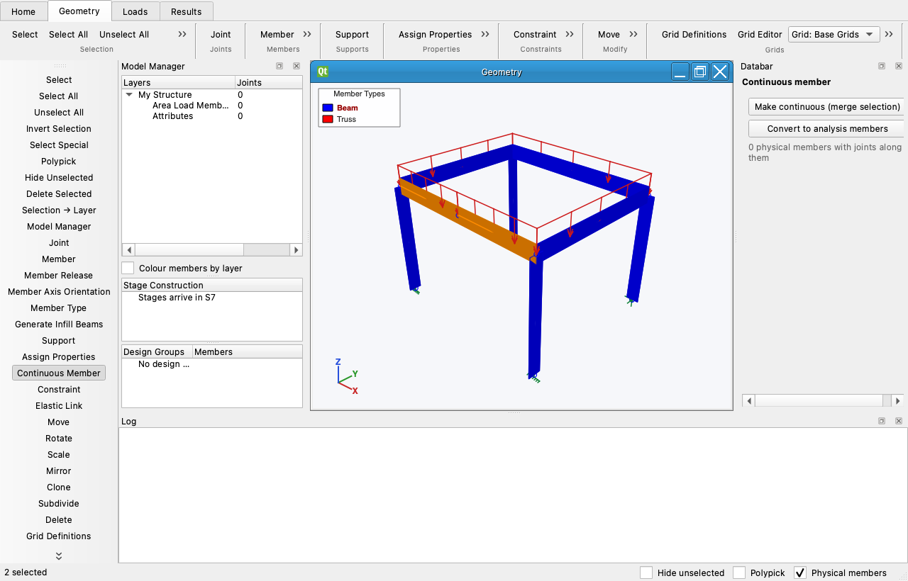
Make continuous merges a straight chain of selected members into one physical member (the inner joints stay along it, loads are carried over, the outer releases and offsets survive). Convert to analysis members splits a physical member at the joints along it. Design lengths follow the physical member.
Support tool (S)
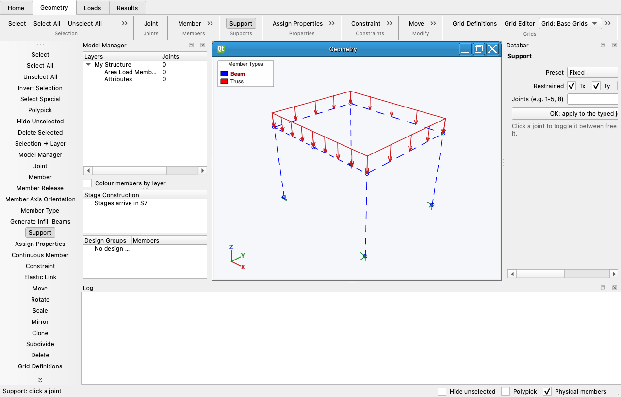
Choose Fixed, Pinned, Roller or a custom set of six restraints, then either click joints or press OK to apply the definition to the joints typed in the range cell ("1-5, 8"), or to the selection when the cell is empty. A click toggles: a joint that already carries exactly this definition becomes free again (S-FRAME Support tool, p3099). Every attribute tool (loads, Assign Properties) has the same range cell and OK, so you can work tool-first or selection-first. Supports are drawn as restraint vectors: a single arrow into the joint for each restrained translation, a double-headed arrow for each restrained rotation, rotated with a skewed support frame; a fully fixed joint is a raked rectangle. Ctrl-click frees the joint. Springs, lumped masses and the support frame are edited in the property inspector. View › Classic Support Symbols switches the drawing to S-FRAME's symbols (help p9): a triangle on every restrained translation axis with a two-line cap for each restrained rotation.
Generate Infill Beams tool
S-FRAME: Generate Infill Beams tool (p2984–2986).
Select the members that form an empty polygon, choose the Direction (X, Y, parallel to the polygon's short or long side, or Any: click or type two joints), the number of beams or a "3@2.5,2@2" spacing, and click inside the polygon. The beams run wall to wall, their end joints inserted on the polygon members, pin-pin by default; one undo entry.
Subdivide (Geometry › Modify)
S-FRAME: Subdivide dialog (p1377–1381).
Select members and choose Subdivide…: each is cut into IJ Links pieces. Average member subdivisions makes every count even and the pieces as close as possible to the longest member's, as S-FRAME describes. With the Physical Members switch on the joints go along the physical member; off, it is split into analysis members.
Geometric Labels (View)
S-FRAME: Geometric Labels dialog (p1555–1556), Display of object numbers (p524).
View › Labels writes joint and member numbers as plain numbers. View › Geometric Labels… chooses more: joint numbers, and for members their numbers, section names, material ids or type, plus member lengths, for all objects or only the selected ones.
Assign Properties, Modify, Constraints
Assign Properties paints a section, material, type, beta angle, releases or offsets onto clicked members.
Reading axes and releases off the picture
S-FRAME: Display local axes (p2925), Display angle gamma (p2919), Display releases (p2930), Multiple Options (p1557).
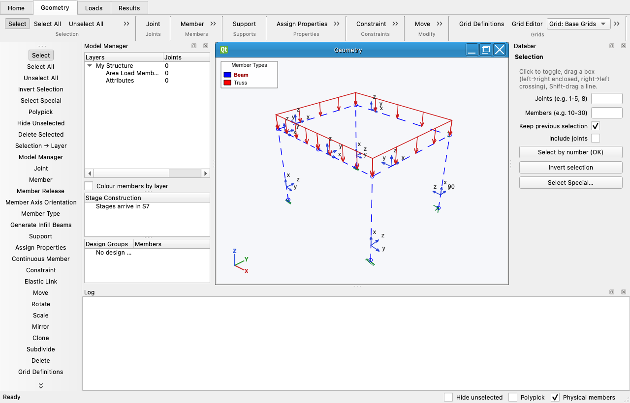
View › Local Axes draws each member's local x, y, z triad near its I end, in blue, with the letters at the tips. A member with a non-zero beta angle (S-FRAME's angle gamma) shows the angle in degrees and its zero-angle z axis dotted, so the rotation can be read at a glance. View › Releases (on by default, as in S-FRAME) draws a green pin semi-circle at every released member end: in the x–y plane for a strong-axis (Mz) release, in the x–z plane for a weak-axis (My) release, both for a pin; a torsion release is a small ring around the axis. Move / Rotate / Scale / Mirror / Clone act on the selection with the values of their Databar. Constraint makes a rigid diaphragm, rigid body or equal-DOF set from a master joint and the selected slaves; Elastic Link joins two joints with six spring stiffnesses.
Delete
Members go first, then only the joints that are no longer attached to anything — attached joints stay, with a note in the status bar.